 Solar Charge Controllers
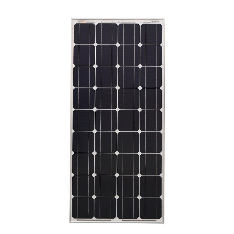 Rigid Solar Panels
 Lightweight Solar Panels
 ABS
ABS Tile & Tin
 Ground Mounting
 See All
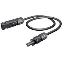 Solar Cables
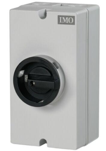 Solar Isolators
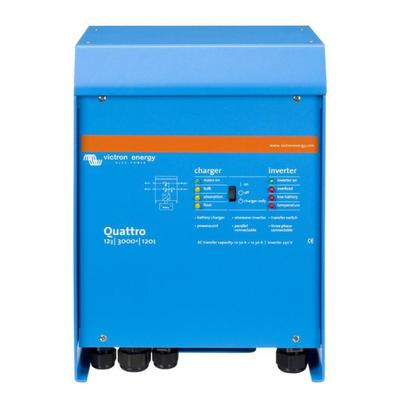 Inverter Chargers
 Inverters
 Battery Chargers
 DC/DC Chargers
 12V lithium batteries
 24V lithium batteries
 36V lithium batteries
 48V lithium batteries
 Battery Monitors
 Battery Cables
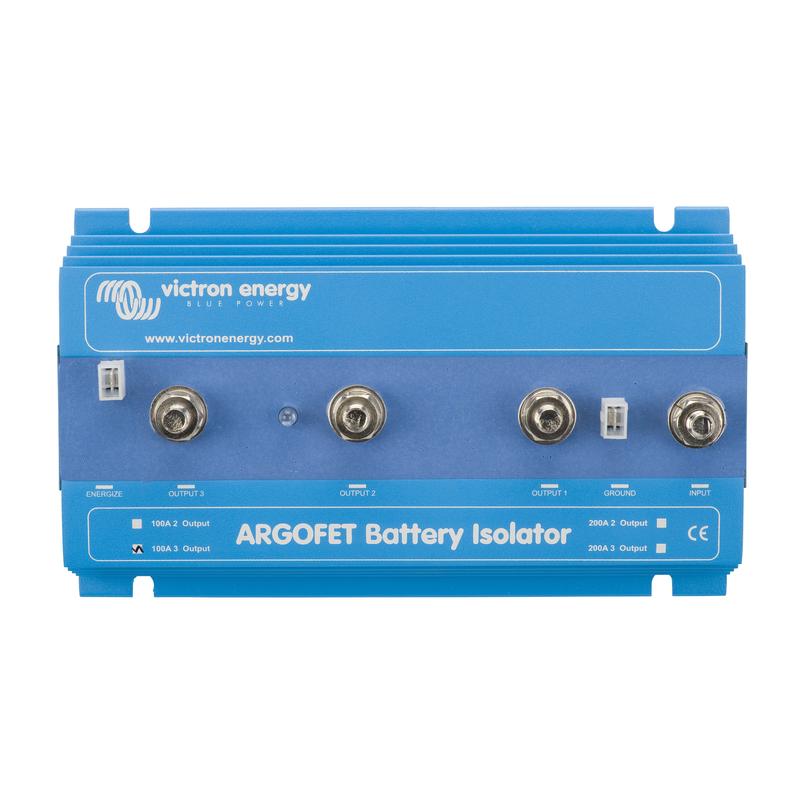 Battery Isolators
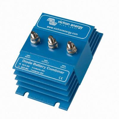 Battery Combiners
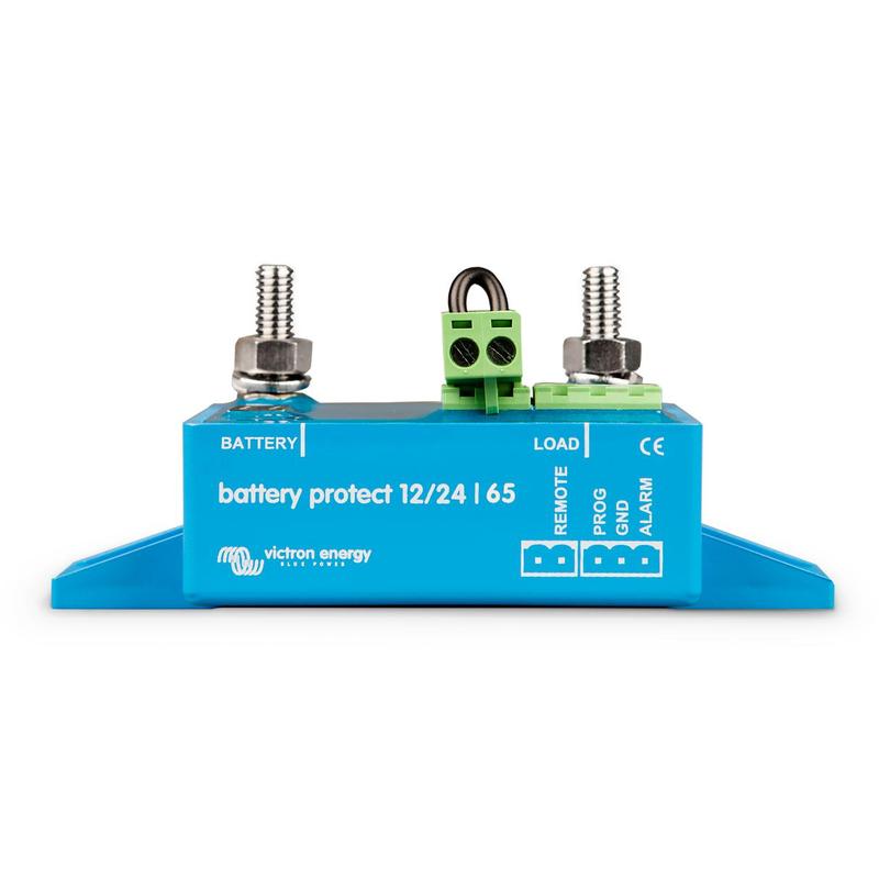 Low Voltage Disconnection
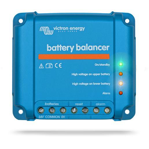 Battery Balancer
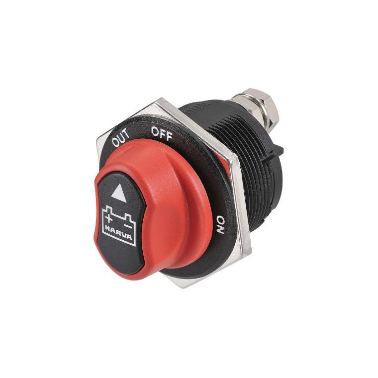 Battery Switches
 Power Cables
 Comms Cables
 Bus Bars
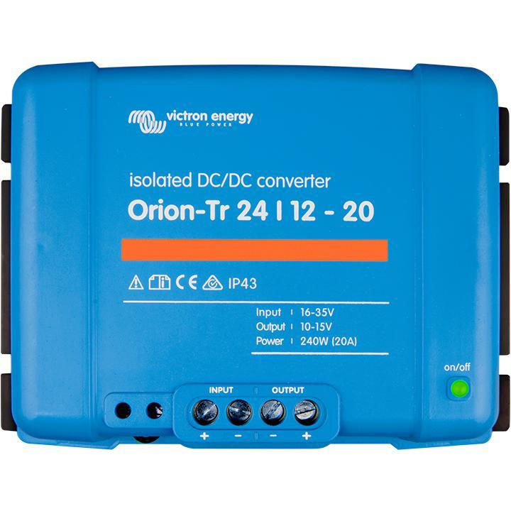 Converters
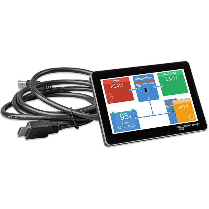 Victron GX Devices
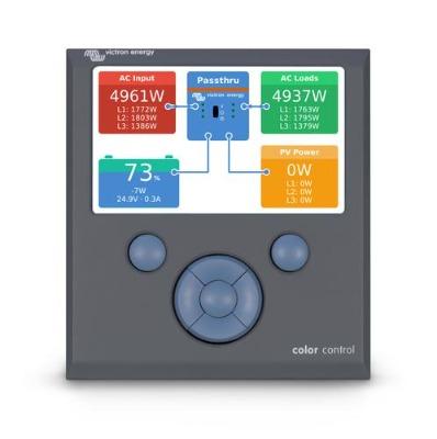 Remote Control Panels
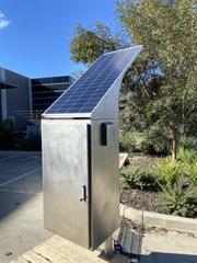 Custom Designs
 Solar Lighting
 Solar Skids
 Solar Trailers
 Portable Power Packs
 Containerised Off Grid Power Systems
 Cable and Fuse Calculator
 Cable Size Calculator
 Main Battery Fuse/Isolator Calc
 Solar Charge Controller Calc
 System Size Calculator
 Technical Info
 How DC/DC Chargers Work: Charging a House Battery from the Alternator
 Offgrid Battery Isolator "Loopback" Wiring - What is it and why do you need it?
 Shunt-Based Battery Monitoring: A Comprehensive Guide
 Inverter/Chargers vs. Normal Inverters: A Deep Dive into Technical Details
 Understanding Solar Panel Wiring: Series vs. Parallel
 RV and Vehicle Kits
 Small Off-Grid Kits
 Medium Off-Grid Kits
 Large Off-Grid Kits


US3000B is a ESS battery system provided by Pylontech. It’s designed around providing a longer service life at higher power output/density per module. Besides its high storage capacity and ease of installation, it provides the ability to scale up to commercial-sized storage systems and be used effectively in these high power demand environments.
Optional accessories:
| Basic Parameters | US3000B |
| Nominal Voltage (V) | 48 |
| Nominal Capacity (Wh) | 3552 |
| Usable Capacity (Wh) | 3200 |
| Dimension (mm) | 442*420*132 |
| Weight (Kg) | 32 |
| Discharge Voltage (V) | 45 ~ 53.5 |
| Charge Voltage (V) | 52.5 ~ 53.5 |
| Recommend Charge/Discharge Current (A) | 37 |
| Max. Charge/Discharge Current (A) | 74 |
| Peak Charge/Discharge Current (A) | 100A@15sec |
| Communication | RS485, CAN |
| Configuration (max. in 1 battery group) | 8pcs |
| Working Temperature | 0C~50C Charge / -10C~50C Discharge |
| Protective class | IP20 |
| Cycle Life | >6,000 25ć |
| Design life | 10+ Years (25C/77F) |
Victron & Pylontech US3000
The combination of Victron products with Pylontech lithium batteries has been tested and certified by the Victron and Pylontech R&D departments.
The Pylontech includes a Battery Management System (BMS) with each battery module. This interfaces with the VictronGX deviceand can support multiple battery modules connected in parallel.
1. Product & system compatibility

| Battery | UP2500* | US2000 (Plus/C) | US3000(C) | UP5000 | Force-L1 |
|---|---|---|---|---|---|
| Nominal voltage | 24V | 48V | 48V | 48V | 48V |
| Module capacity | 2.55 kWh | 2.4 kWh | 3.5 kWh | 4.8 kwh | 3.55 kWh |
* Note that UP2500 came in two versions, UP2500NA01V00101 does not have a CANBUS port, and IS NOT supported by Victron. UP2500NB01V00101 released April 2020 has the CANBUS port and IS supported.
1.1 Offgrid, Backup and Energy Storage Systems are possible
Victron + Pylontech can be used for the following system types:
-
Off-grid(DVCC)
-
Grid Backup(DVCCorESS)
-
Energy Storage Systems (ESS) - Self Consumption
1.2 A GX-device is required, eg Cerbo GX or Venus GX (VGX)
It is essential to use the CAN-bus connection of theGX device(e.g. Cerbo GX or CCGX) with the batteries for the keep-alive signal, communication of charge and discharge limits, error codes and state of charge.
For new systems, the minimum required firmware version for theGX Device (e.g. Cerbo GXis v2.42. It is highly recommended to use the latest firmware version on all connected devices, including the GX device Inverter/Charger and MPPTs. There are regular updates to improve performance and reliability.
Legacy systems installed with v2.15 can continue to be used without upgrade as long as they do not present any issues.
1.3 All Multi, MultiPlus, MultiGrid and Quattro are compatible
As long as you are using the appropriate model for the nominal battery voltage, all VE.Bus inverters and inverter/chargers are compatible.
The minimum firmware version for new installations is 469. Thoughupdating to the latest firmwareis recommended where possible, and a necessary first step when troubleshooting issues.
These inverter/charger units must be connected to theGX devicevia the VE.Bus connection port.
Legacy systems installed with VE.Bus firmware 422 can continue to be used without upgrade as long as they do not present any issues.
1.4 All VE.Direct BlueSolar and SmartSolar MPPT Chargers are compatible
For proper operation, the Pylontech battery needs to be able to control the charge current. Therefor it is recommended to use Victron 48V compatible MPPTs models with VE.Direct port for charging.
MPPTs with a VE.Direct port
MPPTs are controlled via theGX device. Make sure theGX deviceruns v2.15 or later, and the MPPTs to 1.37 or the latest available version.
The MPPT requires connection to theGX deviceto regulate charge currents as the batteries require (due to temperature, etc) To test operation, try disconnecting theGX devicefrom the MPPT. After a time-out, the MPPT will stop charging and flash an error code on its LEDs. The error code iserror #67: no BMS.
MPPTs with a VE.Can port
New Model (2019 and later) VE.Can MPPTs are also supported from firmware version 1.06 and above. Be aware that some GX devices (e.g. CCGX) only have a single CANBus interface, and that is required for the battery communications. So if you use a new VE.Can MPPT, it must also be with a GX device that has more than one CANbus interface, e.g. the Cerbo GX.
Old model VE.Can MPPTs (pre 2019) are not supported.
2. Minimum Battery Sizing Recommendations
The charge and discharge rates are managed automatically by the Pylontech battery andGX device.
Using very large solar arrays with battery banks that are too small can exceed the limits of the batteries ability to charge and possibly lead to the BMS triggering over-current alarms.
You must have the minimum number of battery modules to supply the inverters startup inrush surge currents that charge the capacitors when the inverter is first connected, this occurs prior to any loads being connected. There is also the subsequent potential current demands of the loads connected to the inverter. It is much more desirable to have the inverter/charger overload than the battery, as the inverter will automatically recover, whereas the battery may require intervention once in a fault state.
Some suggested battery sizings for common Victron inverter/chargers are listed below. These are suggestions for reliable operation for single phase off grid and are not specified by Pylontech.
Using the above formula, an example of minimum system sizing based on the US2000 battery module is below. Each battery module is approximately 50Ah at 48V, can provide 25A continuous charge and discharge and 100A peak for 1 minute.
| Inverter / Charger Model | Inv continuous watts @ 25 degrees | Inverter peak watts surge rating | Number of Pylontech modules | Battery continuous discharge watt rating | Battery peak discharge watt rating |
|---|---|---|---|---|---|
| Multiplus 48/500/6 | 430 | 900 | 1 | 1200 | 4800 |
| Multiplus 48/800/9 | 700 | 1600 | 1 | 1200 | 4800 |
| Multiplus 48/1200/13 | 1000 | 2400 | 1 | 1200 | 4800 |
| Multiplus 48/3000/35 | 2400 | 6000 | 2 | 2400 | 9600 |
| Multiplus 48/5000/70 | 4000 | 10000 | 4 | 4800 | 19200 |
| Quattro 48/8000/110-100/100 | 6500 | 16000 | 6 | 7200 | 28800 |
| Quattro 48/10000/140-100/100 | 8000 | 20000 | 7 | 8400 | 33600 |
| Quattro 48/15000/200-100/100 | 12000 | 25000 | 10 | 12000 | 48000 |
3. CAN-bus Wiring

You can connect multiple battery modules together to form a single large battery by connecting the RJ-45 cable supplied by Pylontech using the link ports on the battery. This is shown in more detail in theexample wiring diagramand Pylontech manual.
The communications for UP2500 can be paralleled up to 20 modules per string (and cannot use the LV-HUB). Other models can connect up to 8 battery modules (see Pylontech data sheets), in those models when using more than 8 parallel units, some limitations, additional configuration or equipment (e.g. Pylontech LV-Hub) may apply. See your Pylontech dealer, and Pylontech documentation for more details.
The batteries will automatically detect and link to each other, no adjustment of dip switches on the battery module is necessary.
The battery with the empty link port 0 is the master battery.

You must use this port or the batteries will not be recognized
You do not need to set the DIP Switches, leave them down as they are supplied from the factory.
You must use theVE.Can to CAN-bus BMS type B Cable, part number ASS030720018 for connection with US2000/US3000/UP2500; andVE.Can to CAN-bus BMS type A Cable, part number ASS030710018 for connection with US2000C/US3000C/UP5000/Force-L, you cannot use the cable supplied by Pylontech.
Plug the communication cable with the side which is labeled Battery BMS into the Pylontech CAN port of the master battery. Plug the side labeled Victron VE.Can into theGX device.
Then, plug aVE.Can terminatorin the other VE.Can socket on theGX device. Two VE.Can terminators are included with the package of theGX deviceas an accessory, only one is used. Keep the other one as a spare.
More information about the cable can be found inits manual.
Without properly connecting this cable, the battery will not show up on the display of theGX device. The battery will also turn itself off.
It is important to ensure this connection and display of the battery on theGX devicedisplay before attempting firmware updates or settings changes on other devices if they depend on the power supply from the battery. Without this connection, the battery may turn off unexpectedly.
4. GX Device Settings
On theGX device,
-
Select theCAN-bus BMS (500 kbit/s)CAN-profile in the CCGX. Menu path:Settings → Services → CAN-profile.
After properly wiring and setting the correct CAN-bus speed, the Pylontech will be visible as a battery in the device list. If you have multiple batteries a single entry will show up, which represents all batteries:
When the battery is correctly connected this will also set the following values automatically:
| Venus Settings → System Setup Parameter | Value |
|---|---|
| DVCC | ON |
| Shared Voltage Sense | OFF |
| Shared Temperature Sense | OFF |
-
The parameters option within the battery page shows the actual battery charge and discharge limits

This parameters page is also a good place to check that all batteries are connected and working properly. In see the individual battery data sheet for the normal working conditions, e.g. the current limit per cell. For example, If each battery is rated to 25A charge current, and the menu shows a 75A charge current limit ( 75 / 25 = 3 ) means there are 3 Pylontech battery modules connected.
Note that 'details' menu of the battery (e.g. Lowest and Highest cell voltages etc) is not currently supported by Pylontech.
5. VEConfigure Settings
When using the latest firmware on all compatible connected devices, and once the battery module has been detected by the GX device, battery charging parameters (e.g. Maximum Charge Current, Target Battery Voltage, etc) are automatically configured by the Pylontech BMU, and communicated to the rest of the Victron components in the system viaDVCC.
It is possible to override some of these automatic settings to provide additional limitations (e.g. reduce the total charge current that would be provided but the MultiPlus). The following information is provided for that purpose, though is not required for the safe operation of the system.
This section presumes familiarity withVEConfigure software.
Voltages shown are for the 48V model, and should be scaled for the 24V model. The 24V model is an 8-series configuration while the 48V model is a 15-series configuration. Voltages should therefore be scaled by 8/15.
5.1 General tab
-
Check the “Enable battery monitor” function
-
Set the battery capacity to the total capacity of the battery: eg 50Ah times the number of battery modules for the US2000 model.
-
The other parameters (“State of charge when bulk finished” and “Charge efficiency”) can be left to their default setting: They are ignored for a Pylontech installation.
5.2 Charge Settings
Charger tab
| Parameter | Setting |
|---|---|
| Battery type | Lithium |
| Charge curve | Fixed |
| Absorption voltage | 52.0 V |
| Float voltage | 51.0 V |
| Absorption time | 1 Hr |
Note: make sure to double check the float voltage after completing Assistants, and if necessary set it back to 51.0 V.
Note For off-grid use: ignore the 'bms assistant required' warning.
5.3 Inverter Settings
In the Inverter tab of VEConfigure
| VEConfigure Inverter Parameter | Setting |
|---|---|
| DC input low shut-down | 44V |
| DC input low restart | 48V |
| DC input low pre-alarm* | 48V |
* The pre-alarm setting is dependant on your preference and on site specific requirements. You may wish for this to be activated earlier in an off grid situation to allow time to start a backup generator.
ESS System Settings
If you are using the battery as part of agrid connected ESS system, please review theESS Quickstart guideandDesign and Installation Manual.
The settings that are specific to the Pylontech battery in the VEConfigure ESS Assistant are below:
Select the externally managed Lithium battery option

| ESS Parameter | Settings |
|---|---|
| Sustain voltage. | 48V |
| Dynamic cut-off values | set all values to 46V. |
| Restart offset: | 1.2V (Default) |
Due to the reliability of the grid supply and the behaviour of the sustain voltage threshold in ESS; you may wish to suppress the low voltage pre-alarm warning so that it does not trigger every day on its regular deep cycle. SeeESS FAQ Q5- about suppressing the low-voltage alarm.
Hardware Protection Points
In normal operation, the charge parameter limits are set by the Pylontech battery and communicated through the system by theGX deviceto the inverter/charger and MPPT.
-
Low Voltage: When the battery discharges to 44.5V or less, battery protection will turn on.
-
High Voltage: If charging voltage above 54V, battery protection will turn on.
-
Working discharge temperature range is from -10 to 50 degrees celsius.
-
Charging temperature range is from 0 to 50 degrees celsius.
-
Discharge Current Limit set to 0A at 47V, inverter will turn off.
-
Over-charge and Over-discharge Current Limit 102A for 15 seconds, 200A for 0.1 seconds and 400A short circuit current.
If operation is attempted outside the operating range, the battery will disconnect to protect itself.
6. VE.Direct MPPT Settings
In normal operation the MPPT charge characteristics are governed by theGX devicevia DVCC, with instructions from the connected Pylontech battery.
This section presumes familiarity withVictronConnect
The settings below can be set as a precautionary measure.
| MPPT Parameter | Setting |
|---|---|
| Battery voltage. | 48V |
| Absorption voltage | 52V |
7. Example Wiring Diagram

8. Troubleshooting
If the system is not operating correctly, go through these steps.
Step 0. If the Inverter/Charger or GX device does not switch on
As a safety precaution, the inverter/charger will not switch on if theGX deviceis not on. If you are unable to start the system due to a total system blackout / battery shutdown due to low voltage, you may need to disconnect the VE.BUS connection cable between the inverter/charger andGX device.
You can then start the inverter/charger from an external charge source such as a generator or grid connection. Once the inverter/charger has started, it should supply power to the DC terminals and this should start theGX deviceand Pylontech battery again. You will need to then reconnect the VE.Bus Communications cable back to the inverter/charger andGX device.
Step 1. Check that the Pylontech battery is visible on the GX device list
If its not visible, check:
-
GX devicefirmware version (update to latest version, v2.15 or later)
-
CAN-bus communication cabling between Pylontech and Victron system. Make sure that it is in the right way around.
-
Pylontech system is up and running (LEDs are on)
Step 2. Check that the Pylontech battery is ready for use
Check the Max Charge Voltage parameter. This voltage parameter is sent, together with the other three parameters, by the Pylontech system via the CAN-bus cable. They are visible on theGX device: Device List → Pylontech battery → Parameters menu.
Step 3. Check the Pylontech manual
The Pylontech manual contains additional diagnostic and troubleshooting information, specifically around decoding any indicator LEDs.
9. FAQ and Known Issues
The maximum charge and discharge current is limited to 25A, but the data sheet tells me the maximum is 100A.
The maximum current is limited to keep the battery healthy and reach the 10 year guarantee. In off-grid, the inverter can draw more than the 25A limit to run the loads, make sure you have sufficient batteries installed to keep the load per battery around this limit.
After charging the battery the charge current often changes between 0A and 25A.
This is caused by cell balancing inside the battery. This happens with new batteries and after a deep discharge.
My system isn't charging at the rated capacity, or my PV is shutting down
Pylontech's BMS will restrict the Charge Current Limit of the battery in cold weather. The precise temperatures and limits are not published by Pylontech, but anecdotally from reports onVictron Communityit would appear that batteries begin to be limited below 18 degree C, severely limited below 10 degrees C, and completely restricted from charging below 2 degrees C.
You can confirm if this is affecting your installation be entering the Pylontech Battery menu on your GX device, and then the Parameters Menu. This will report the Charge Current Limit (CCL) and Discharge Current Limit (DCL). This information is also logged in the advanced section of the VRM monitoring portal.
My system only charges the battery to 52.4V
When DVCC is enabled, the battery (via the CAN-bms) is responsible for the charge voltage. The Pylontech battery requests a charge voltage of 53.2V. We have however found that in practice this is too high.
The Pylontech battery has 15 cells in series, so 53.2V equates to 3.55V per cell. This is very highly charged and makes the system prone to go overvoltage.
It should also be noted that a LiFePO4 cell stores very little additional energy above 3.45V.
For this reason we opted to override the BMS and cap the voltage at 52.4V. This sacrifices almost none of the capacity and greatly improves the stability of the system.
The battery won't charge to 100%
Also see the question above. The state of charge of the battery is estimated based on the overall voltage and on how well balanced the internal cells are. Because we cap the battery voltage at 52.4V, the state of charge will sometimes rise very slowly once it reaches the mid-90s. This is normal and usually resolves over time.
'Internal Error' shown on battery status
The 'Internal Error' shown in battery status is not a critical error. This only defines that within a battery system, some of the slave batteries are offline(which is due to these modules have been discharged to an extremely low SOC or being in idle mode for more than 72hrs), once the system is available for a charging activity such an error will be automatically eliminated.
10. Further Information
Further community discussion about installing and using Pylontech and Victron can be found atVictron Community, use the topic label 'Pylontech